12 Results
View results:
Sort by:

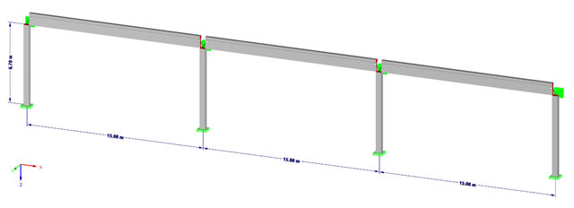
This article describes how a flat slab of a residential building is modeled in RFEM 6 and designed according to Eurocode 2. The plate is 24 cm thick and is supported by 45/45/300 cm columns at distances of 6.75 m in both the X and Y directions (Image 1). The columns are modeled as elastic nodal supports by determining the spring stiffness based on the boundary conditions (Image 2). C35/45 concrete and B 500 S (A) reinforcing steel are selected as the materials for the design.
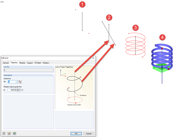
In RFEM, you can create screw lines using the "Trajectory" type line. To do this, you need a center line/guide line around which the line can be modeled, as well as a start and end point. Then, you can create a "Trajectory" type line between the start and end points; this initially appears as a straight line.

An elastic foundation can be applied to a member. Thus, the influence of the soil is usually included in the modeling. Member elastic foundations can only be defined for the "Beam" member type.

For a timber connection as shown in Figure 01, you can take into account the torsional spring rigidity (spring stiffness for rotation) of the connections. You can determine it by means of the slip modulus of the fastener and the polar moment of inertia of the connection.
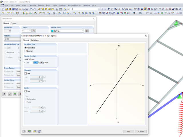
The RFEM5 and RSTAB8 programs offer a "Spring" option when defining a member under the member types.

In the case of open cross-sections, the torsional load is removed mainly via secondary torsion, since the St. Venant torsional stiffness is low compared to the warping stiffness. Therefore, warping stiffeners in the cross-section are particularly interesting for the lateral-torsional buckling analysis, as they can significantly reduce the rotation. For this, end plates or welded stiffeners and sections are suitable.
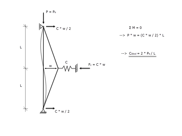
If a member is supported laterally to prevent buckling due to a compressive axial force, it must be ensured that the lateral support is actually able to prevent buckling. Therefore, the aim of this article is to determine the ideal spring stiffness of a lateral support using the Winter model.
With RF-FOUNDATION Pro, it is possible to determine the settlements of single foundations and resulting spring stiffnesses of the nodal supports. These spring stiffnesses can be exported into the RFEM model and used for further analyses.
![Time-Dependent Settlement Components [2]](/en/webimage/009673/2419908/01-en-png-png.png?mw=640&hash=5e657e3feb5c1bb6d21727468dd85d91e1c9f29f)
For the serviceability limit state design according to Section 6.6 of Eurocode EN 1997‑1, settlement has to be calculated for spread foundations. RF-/FOUNDATION Pro allows you to perform the settlement calculation for a single foundation. For this, you can chose between an elastic and a solid foundation. By defining a soil profile, it is possible to consider several soil layers under the foundation base. The results of the settlement, foundation tilting, and vertical soil contact stress distribution are displayed graphically and in tables to provide a quick and clear overview of the calculation performed. In addition to the design of the foundation settlement in RF-/FOUNDATION Pro, the structural analysis determines the representative spring constants for the support and can be exported to the structural model of RFEM or RSTAB.
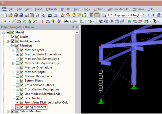
You can display spring members in the Display Navigator. A spring member is displayed as a helix by default. Clear the "Spring Members" check box to display them as normal lines.
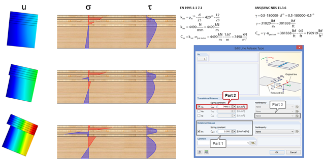
In order to represent the stiffness of the entire structure correctly, you can consider shear coupling between the ceiling and the downstand beam using the line release. This way, you can define a spring constant, thus avoiding the replacement system by using coupling members. The spring constant results from the shift modulus of the fastener, which can be determined according to EN 1995-1-1 or ANSI/AWC NDS, for example.
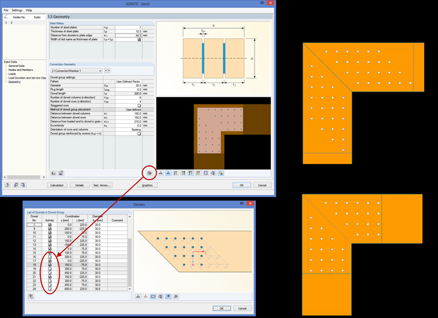
In RF‑/JOINTS Timber, you can remove an individual dowel from the calculation, thus creating any dowel layout. The calculation disregards these removed dowels for the ultimate limit state design, as well as for the net timber cross‑section analysis and the rotational spring stiffness determination.